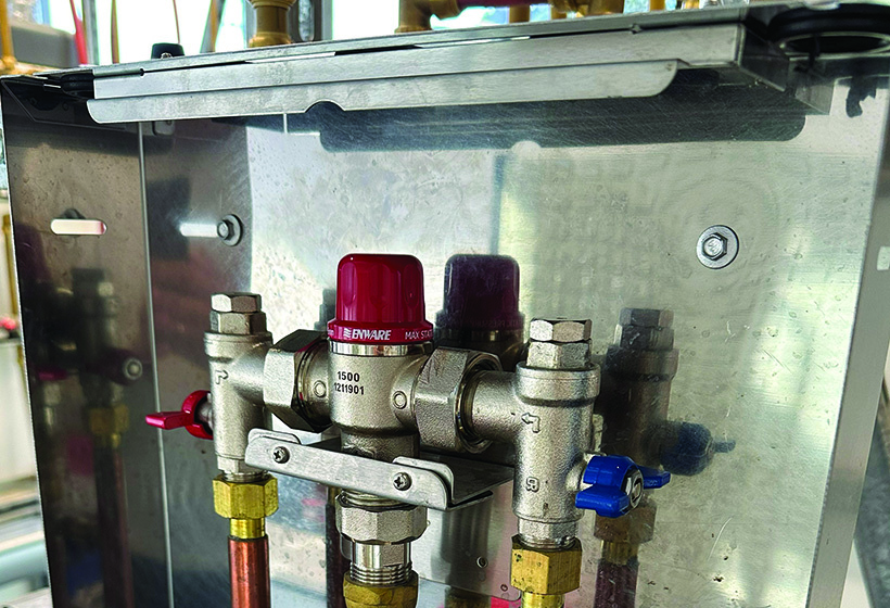
Have you ever wondered how to correctly locate and install a Thermostatic Mixing Valve? You’re not alone. To assist, Master Plumbers technical advisor Sam Welsh presents what you need to know from the AS/NZS 3500.4:2021 and the NCC warm-water handbook.

Let’s start with the associated valves, which are required to correctly install a thermostatic mixing valve (TMV). Each TMV has an isolating stop tap, line strainer and crossflow prevention device (non-return) valve fitted to both the hot and cold water-supply lines. Having these valves will make it easy to perform
TMV maintenance. Also, there is to be no branch line offtake between the non-integral isolating valve and the inlet to the TMV. (Figure 1)
 Figure 1
Multiple TMVs
When multiple TMV’s are installed in the same location, a stop tap, line strainer and non-return valve may control each of the hot and cold supplies to more than one TMV, provided each of the individual TMV is controlled by an isolating stop tap/valve and installed with a crossflow non-return valve. All TMVs must be supported independently of the piping. (Figure 3)
 Figure 3
Accessibility
AS/NZS 3500.4:2021 states that each TMV and each associated valve, pressure control or temperature control shall be readily accessible, which it defines as: “accessible without hazard, undue difficulty, or use of a tool”. (And, in this case, a ladder is a tool.) To add to this it states, it needs to be suitably accessible within its box/surrounding area, unlike figure 2. For those who hold the specialised class of Thermostatic mixing valve servicing, you can find the information you need to know about servicing in AS 4032.3:2022 the field testing and maintenance standard.TMV positioning
You must have the recommended, minimum pipe length of 1m from the TMV to the first outlet. This distance will reduce the possibility of a heat spike and will assist in minimising any temperature increase, should the failsafe function of the TMV be initiated. The 1m length of pipe will also assist in dissipating the heat of the hotter water. Finally, how far away can I install a TMV?
The distance is limited by the pipe branch. The rationale is a pipe branch from a TMV should contain no more than 2L of water or exceed 10-lineal meters. As an example, 20-lineal meters of 15mm copper pipe would hold a volume of 2L.
Adhering to this volume will ensure heat loss and microbial growth is minimised, unless a heat-trace system is used to maintain system temperature. A pipe material’s heat-loss properties, the volume of water and valve specifications should also be considered when determining branch lengths.
Figure 2 shows a poor installation. The TMV is not installed in a way that will make it easily accessible to service the valve.
 Figure 2
Share this Article


